jaydrive2000
Number of posts : 83
Registration date : 2012-09-05
 | | Subject: RDM6300 via Arduino - Example Wiring (Arduino Code to follow) 30/4/2013, 16:38 | |
| Hi all. I've been working on a 6 way lane scanner via a single Arduino Uno, with 6 instances of RDM6300 RFID readers. Here's how you need to connect each of the RDM6300 units 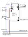 Make sure you have them together on the common serial line, +5V Common Line, and Ground line. The BC549 NPN is a transistor which can be controlled by arduino, controlling if the device is on or off, and same again as to wether it is connected to the transmission line. The Purple Device Select connection SHOULD NOT BE COMMON and there is one for each device. The activity LED's resistor is something you need to work out based on the LED you use, but the output from that point is 5v. The LED will turn on when the device is active, and will 'blink' whilst the reader scans the tag. I will share some Arduino Code a little later on how to get the Arduino to talk to these and as a result, get you a RFID reader system for a good price. The readers I'm using cost me around £7 per unit!
Last edited by jaydrive2000 on 30/4/2013, 16:51; edited 1 time in total | |
|
jaydrive2000
Number of posts : 83
Registration date : 2012-09-05
| | Subject: Re: RDM6300 via Arduino - Example Wiring (Arduino Code to follow) 30/4/2013, 16:50 | |
| NOTE - My club uses Scalextric Digital, so we're limited to 6 lanes. It is possible to edit this code to accomodate further lanes - but please don't message me asking for support because I may not get to answer for a while. Here's the Arduino Code... IMPORTANT WIRING CONNECTIONS Attach the Blue COMMON Serial Line to Arduino Uno's PIN 2 (DIGITAL) Attach the +5V COMMON Line to Arduiono Uno's +5V output or alternative source Attach the GROUND COMMON Line to Arduiono Uno's GROUND output or alternative source For the Lane 1 Scanner, attach the PURPLE DEVICE SELECT line to PIN 4 (DIGITAL) For the Lane 2 Scanner, attach the PURPLE DEVICE SELECT line to PIN 5 (DIGITAL) For the Lane 3 Scanner, attach the PURPLE DEVICE SELECT line to PIN 6 (DIGITAL) For the Lane 4 Scanner, attach the PURPLE DEVICE SELECT line to PIN 7 (DIGITAL) For the Lane 5 Scanner, attach the PURPLE DEVICE SELECT line to PIN 8 (DIGITAL) For the Lane 6 Scanner, attach the PURPLE DEVICE SELECT line to PIN 9 (DIGITAL) ** IMPORTANT NOTE ** This code does NOT have means of error checking. Any tag pulled away or entered into the RFID field when the device is enabled, will result in corrupted data being sent along the transmission line to Arduino Uno. I intend to solve this, but it's a case of when I get time. ** LANE TAG ID's ** If you are a competent Arduino coder, and can edit arrays, you'll notice an array holding 6 RFID strings. Edit these to match your PCLapCounter's RFID Lane Tags. If you are not a coder, enter the following strings into PCLapCounter to match with the appropriate lane.... LANE 1 - 6E0084D539 LANE 2 - 6E0084999C LANE 3 - 6D00091BE1 LANE 4 - 6D0009311E LANE 5 - 6E0084A84C LANE 6 - 6D00094B1A PLEASE DO NOT MESSAGE ME FOR SUPPORT, I am not able to provide it - you use the code and wiring diagram at your own risk! - Code:
-
char inChar; // Store the single character pulled in from the RFID Serial Port here
// Serial Library
#include <SoftwareSerial.h>
SoftwareSerial RfidData(2,3); // Com to Scanner TX's tied together
int LoopCounter; //Keep track of number of times to loop here
int LaneCounter; //Keep track of which lane we're scanning here
String TagJustScanned = ""; // store the tag just scanned here
int PowerControlLane[6] = {4,5,6,7,8,9}; // set the pins which will control the power to the RFID Scanners
String LaneScannedTag[6] = {"","","","","",""}; // set these to blank as the system hasn't scanned any tags
//PCLAP COUNTER LANE TAGS - LANE 1 - LANE 2 - LANE 3 - LANE 4 - LANE 5 - LANE 6
String LaneAssignedTag[6] = {"6E0084D539","6E0084999C","6D00091BE1","6D0009311E","6E0084A84C","6D00094B1A"}; // Assign the previously determined RFID Seqeunces associated with a specific lane (Left most set of numbers is for lane 1, then lane 2, etc)
//-------------------------------------------------------------------------------------
// Intial Set Up
//-------------------------------------------------------------------------------------
void setup() // Let's get the system ready before we actually start doing anything
{
Serial.begin(9600); // Turn on the serial port connected to the computer at 9600bps
RfidData.begin(9600); // Turn on the serial port that connects to the RFID Scanners at 9600bps
for (LaneCounter = 0; LaneCounter < 6; LaneCounter ++) // Go through each lane and do the following..
{
pinMode(PowerControlLane[LaneCounter],OUTPUT); // Set all the pins to be outputs
digitalWrite(PowerControlLane[LaneCounter],LOW); // Turn all these pins LOW to turn off all the RFID Scanners
}
//end loop
} //end of setup()
//-----------------------------------------------------------------------------------------
//Main program loop
//-----------------------------------------------------------------------------------------
void loop() // This is the main program
{
for (LaneCounter = 0; LaneCounter < 6; LaneCounter ++) // enter a loop sequence as long as "LaneCounter"'s values is less than 6
{
lanescan(LaneCounter); // Activate the RFID Scanner Sequence for the matching lane and pull data in
delay(100); // wait for 1/10th of a second before moving to the next lane.
}
}
void lanescan(int LaneNumber) // This is the bit the activates a scanner, pulls in the data, checks it, and then turns it off, send the data to PC LapCounter
{
digitalWrite(PowerControlLane[LaneNumber],HIGH); // turn reader on
delay(200); // wait for the reader to settle
TagJustScanned = ""; // Clear any previous data
if (RfidData.available() > 0) // if there is data on the virtual serial port
{
for (LoopCounter = 0; LoopCounter < 11; LoopCounter ++)
{
delay(50); // wait a bit
inChar = RfidData.read(); // Get the next character from the virtual serial port
TagJustScanned += inChar; // throw it on the end of the string we're building to use.
}
//This next loop removes the preceeding blank that is acquired upon reading in from the Serial Port for RFIDDATA
for (LoopCounter = 0; LoopCounter < 11; LoopCounter ++)
{
TagJustScanned[LoopCounter] = TagJustScanned[LoopCounter + 1]; // The current character in the string will now become the character to it's immediate right.
}
}
RfidData.flush(); // clear the stream of data
// The next 2 if statements prevent the RFID tag being sent more than necessary.
// It will only resend the tag if it was removed and then scanned again, when the power was turned on during
// multiplexing.
if ((LaneScannedTag[LaneNumber] != TagJustScanned) && (TagJustScanned != "")) // If the tag scanned is different to the one previous scanned, but is ALSO not "Blank" then
{
LaneScannedTag[LaneNumber] = TagJustScanned; // update my records of which tag just got scanned
SendPCLCCommand(LaneNumber); // Send it to PCLapCounter
};
if (TagJustScanned == "") // If I didn't get detect a tag just now
{
LaneScannedTag[LaneNumber] = TagJustScanned; // update my records but don't bother sending anything
};
digitalWrite(PowerControlLane[LaneNumber],LOW); // Turn Reader Off
delay(200); // allow time for reader to power down fully
RfidData.flush(); // Just empty the data stream from the RFID Scanners
Serial.flush(); // And empty the Serial Buffer to the PC now that I'm done with it.
}
void SendPCLCCommand(int LaneNumber)
{
Serial.println("RF" + LaneScannedTag[LaneNumber]); // Send the PC LapCounter Command out with the RFID Tag's number correctly formatted
delay(10); // wait a bit to let PCLC handle things
Serial.println("RF" + LaneAssignedTag[LaneNumber]); // Send the PC LapCounter Command to say what lane this tag is being allocated to.
delay(10);
}
| |
|