Pepsikid

Number of posts : 19
Age : 72
Localisation : Port Charlotte Florida USA
Registration date : 2014-08-20
 | | Subject: Schema to connect external button to phidget 26/8/2014, 02:16 | |
| The Phidget is used to interface your device to the software (PCLC). Inputs, the "signal" to preform an action originates from the device and is passed INTO the computer (software) via the Phidget. Outputs, the "signal" originates in the computer (software) and is passed OUT to a device for action via the Phidget. The key to wiring a Phidget is understanding what type of "signal" needs to be passed (In or Out), from there each type of signal needs to be attached to the corresponding type of pin and generally is a three (3) element process: Power supply, Device, and a Phidget Pin. The BASIC model states: (-) post of POWER goes to "G" on Phidget (always use closest "G" pin on correct side (In or Out), (+) post goes to one side of the device (normally "+" side); (+) lead of DEVICE goes to power, other lead goes to the Phidget pin that will control the action signal. "G" is not "Ground" per say, but a "collector" that acts as one, but believe G's on In & Out are different. Using process of substitution to the basic model where POWER DEVICE and PIN, can be changed to correct values for your application, your only limit is the number of pins, and/or your use of them. For those considering a Phidget purchase, with cost being your detractor... for less than the price of one "good car" for your Track, your Track can make ALL your car's and events look good. 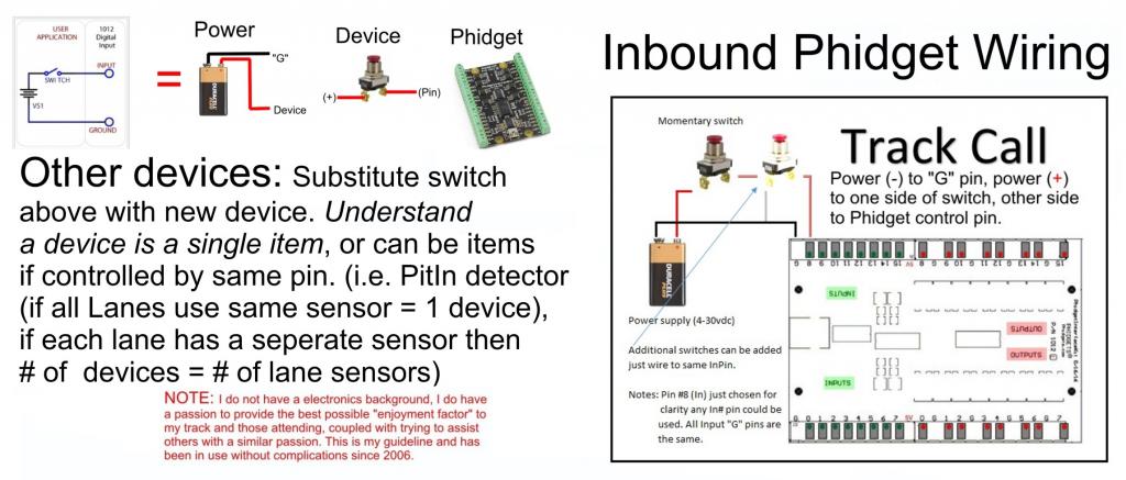 | |
|