Pc Lap Counter
Would you like to react to this message? Create an account in a few clicks or log in to continue.
Pc Lap Counter

Logiciel de comptage
 
HomeHome  SearchSearch  Latest imagesLatest images  RegisterRegister  Log in  


 Schema to connect detector to Phidget 8/8/8

Go down 
4 posters
AuthorMessage
guy

guy


Number of posts : 2296
Localisation : Belgique
Registration date : 2006-01-25

Schema to connect detector to Phidget 8/8/8 Empty
PostSubject: Schema to connect detector to Phidget 8/8/8   Schema to connect detector to Phidget 8/8/8 Empty6/12/2007, 20:50

Posted by Slotmanege:


As promised I would post our used hardware scheme here.

We have been struggling with our hardware for some time now. And it seems to be working at last (no more missed laps). But to be 100% sure we have to do some more testing and do some final adjustments. Things we have to do (final adjustments) = making use of shielded data-cables. Because of many electro magnetic influences (power cables and electro motors) it is best to shield the the data lines.

We make use of the Phidget 8/8/8. And for lap counting we use the digital inputs because they are 'faster' then the analog inputs.

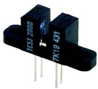
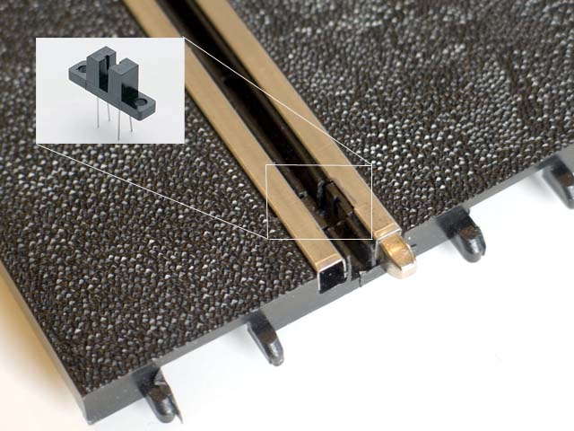
Below you can see the slot-mounted IR-sensors (CNY37 = TCST2000) which we are using on our track.
Using these sensors you don't need a separate light-source above the sensors because the sensors actually have their own sender and receiver unit.

Schema to connect detector to Phidget 8/8/8 Test
Schema to connect detector to Phidget 8/8/8 TCST2000
Schema to connect detector to Phidget 8/8/8 Slottedswitch

Anyway... Here is the electrical scheme:

Schema to connect detector to Phidget 8/8/8 Schakeling1

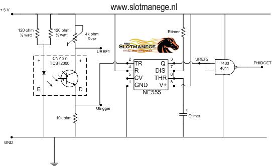
I will try to explain it here:

In 'idle' state... so no slotcars racing on the track the IR sensor actually act as a closed switch. This means that the voltage on label UREF1 is about 3,6 volts. The Rvar is a potentiometer (variable resistor). The 'best' value to set the Rvar is around 4k. It is wise to install a Rvar with a larger value then 4k (minimal value = 5k). In this way you can 'fine-tune' the Rvar to get the desired 3,6 volts on label UREF1. When using a non variable, fixed resistor for Rvar it is best to keep it on 4k.
In idle state the rest of the electronics are also idle and the output (label PHIDGET) voltage is = +5 Volts.

Whenever a guidance-flag of a slotcar passes the sensor the IR light-beam is interrupted and the sensor acts as a closed switch (for as long as the beam is interrupted). This causes a voltage drop on label Utrigger from 3,6 volts down to 0 volts.
The NE555 (timer IC) reacts on this voltage drop (NE555 reacts whenever the voltage drops more then 2/3 of V+) and starts the timer. The timer is used to extend the length of the pulse, long enough that the Phidget 8/8/8 can read it correctly. The length of the pulse = interval time (t) is given by: t = 1.1 x Rtimer x Ctimer. (C is a electrolytic capacitor). This means that the voltage on label UREF2 is +5 Volts (during the interval time).

The last part of the diagram shows a logical gate. We make use of the 4011 CMOS NAND gate (but a TTL NAND gate from the 7400 family should also do the trick). The NAND gate converts the +5 Volts from label UREF2 towards the 0 volts (label PHIDGET) which is needed to trigger the Phidget 8/8/8 digital input.
If you want to use this diagram with the Phidget 0/16/16 you easily replace the NAND with an AND logical gate.

More info about NE555 timer = http://en.wikipedia.org/wiki/555_timer_IC
More info about 7400 logical gates = http://en.wikipedia.org/wiki/7400_series
More info about 4000 logical gates = http://en.wikipedia.org/wiki/4000_series

The only flaw of the used sensors is that these sensors do not recognize blue and white guidance-flags. Only black ones !!!
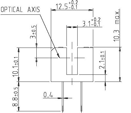
And we did remove some of the top of the sensors so the 'optical axis' becomes closer to the track.

If you have questions or remarks, please ask !

We are also very interrested in your opinions about our hardware? Perhaps we still can improve!

Regards,
Danny
http://www.slotmanege.nl (sorry... only in Dutch)
Back to top Go down
http://www.pclapcounter.be
lars_jacobsen


Number of posts : 92
Registration date : 2006-10-02

Schema to connect detector to Phidget 8/8/8 Empty
PostSubject: Re: Schema to connect detector to Phidget 8/8/8   Schema to connect detector to Phidget 8/8/8 Empty30/4/2008, 00:40

this is exactly the setup we are using - it is perfect for timing slotcars but does have 1 downside

You have to use black guides - our expierence show that purple or white guides do not break the ir sufficiently to detect as a passthrough

But besides that it is by far the best detection method

:-)
Back to top Go down
Bjarne


Number of posts : 14
Localisation : Denmark
Registration date : 2007-11-30

Schema to connect detector to Phidget 8/8/8 Empty
PostSubject: Re: Schema to connect detector to Phidget 8/8/8   Schema to connect detector to Phidget 8/8/8 Empty30/4/2008, 08:02

What about reducing the current to the transmitter. Then maybe the light can't get through the white and purble guides Question Idea

regards
Bjarne Jørgensen
Back to top Go down
lars_jacobsen


Number of posts : 92
Registration date : 2006-10-02

Schema to connect detector to Phidget 8/8/8 Empty
PostSubject: Re: Schema to connect detector to Phidget 8/8/8   Schema to connect detector to Phidget 8/8/8 Empty30/4/2008, 11:33

Hi Bjarne

Unfortunatelly spoke to our "transmitter" supplier -and it's either on or off, not way in between

:-(

But we are adding an additional light brigde now in order to have pit stop possibility and to use for races where these guides are used

:-)
Back to top Go down
Bjarne


Number of posts : 14
Localisation : Denmark
Registration date : 2007-11-30

Schema to connect detector to Phidget 8/8/8 Empty
PostSubject: Re: Schema to connect detector to Phidget 8/8/8   Schema to connect detector to Phidget 8/8/8 Empty2/5/2008, 11:22

Hi Lars

acording to your diagram, I will say that you can put a resistor i series whit the two 120ohms that gor to the emitter. That would reduce the current and the light intensity Very Happy

regards Bjarne
Back to top Go down
larryg


Number of posts : 1
Registration date : 2009-02-01

Schema to connect detector to Phidget 8/8/8 Empty
PostSubject: Re: Schema to connect detector to Phidget 8/8/8   Schema to connect detector to Phidget 8/8/8 Empty1/2/2009, 20:01

Quote :
Hi Lars

acording to your diagram, I will say that you can put a resistor i series whit the two 120ohms that gor to the emitter. That would reduce the current and the light intensity

regards Bjarne

As the IR emitter is either on or off, regardless of the resitor value, changing the resistor value will not have any effect.

The problem is likely due to the nearness of IR and blue/white in the color spectrum.
A blue / white guidance-flag will not block the IR wave length as good as a black guidance-flag.

Try IR-reciever LPT80A and a simple (red) LED stead of the CNY37, works for me....

Regards,
Laurent
Back to top Go down
Sponsored content


Schema to connect detector to Phidget 8/8/8 Empty
PostSubject: Re: Schema to connect detector to Phidget 8/8/8   Schema to connect detector to Phidget 8/8/8 Empty

Back to top Go down
 
Schema to connect detector to Phidget 8/8/8
Back to top 
Page 1 of 1
 Similar topics
-
» Schema to connect detector to Phidget 0/16/16
» Schema to connect Ds light bridge to Phidget
» Schema to connect external button to phidget
» Schema to connect Ds light bridge to Phidget
» Schema to connect the Lap Counter ref 30342 to the computer

Permissions in this forum:You cannot reply to topics in this forum
Pc Lap Counter :: Hardware :: Phidgets interface kit-
Jump to: